Home > ScopeTool software
ScopeTool (TM) - Microscope Automation Software
Download
V 3.0
Download
V 4.3
Introduction
Device
control commands
Remember
and relocate
Scanning
Additional
functionality in the user interface
Symbolic
Constants
Parameters
describing hardware, specimen, and scanning
How to adjust parameters
Built-in interpreter
Controlling
ScopeTool from different software environments
Integration of components from different vendors in automated microscopy
Low level
controller commands for IM483I
Low level controller commands for
EZHR17EN
Introduction
ScopeTool is a software component that links the TOFRA hardware and the environment from which
the microscope hardware must be controlled. This environment could be one or combination of:
- Direct user interaction.
- User application written in a programming language.
- An image processing package.
- Other application (e.g., MS Excel), which serves as a host.
ScopeTool is a Windows ActiveX executable. It is also a DDE server. It can be called from any
application, which is an ActiveX client or a DDE client. ScopeTool encapsulates all the hardware-specific knowledge
and provides the client application with a simple interface. It has one method available to the client - execute
a command string and return the result string.
The command set is designed to contain everything that a user might want to do with the provided hardware. At the
same time it does not burden the client application with the hardware details that the client does not want and
need to know.
ScopeTool can run invisible or with the user interface. The mode can be changed during execution by the user or
by a command from the client.
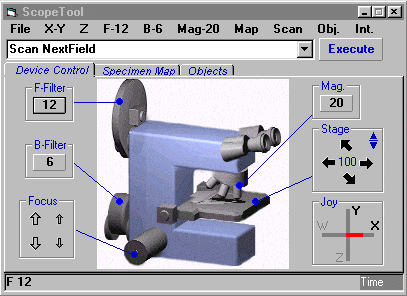
The user interface visually represents an automated microscopy system with motorized stage,
focus, and fluorescence and brightfield filter wheels. Different tabs represent different functional groups provided
by ScopeTool. The text box and command button at the top are for entering and execution of ScopeTool commands -
the same commands as those available to client applications. |


 |
Device
control commands
(All distances are in
microns)
Stage
|
XY Rel <distance-x> <distance-y> |
Move stage by the given distances in X and Y directions relative to the current position. |
|
XY <destination-x> <destination-y> |
Move
stage to the position given by X and Y coordinates. |
|
XY Move <speed-x> <speed-y>
|
Move stage with the given constant speeds in X and Y directions. |
|
XY Origin |
Set stage position counter to zero. |
|
XY Home
|
Home stage. Stage is moved to limit switches in the top left corner and position counter is set to zero. |
|
XY Stop |
Stop the stage move. |
|
XY Wait |
Wait for completion of the current stage move. |
|
XY
? |
Return a string with decimal representation of the current stage position. |
|
XY
?? |
Return a string containing "XY" followed by decimal representation of the current stage position. |
Focus
|
Z Rel <distance-z> |
Move focus by the given distance in microns relative to the current position. |
|
Z <destination-z> |
Move focus to the position given by Z coordinate. |
|
Z Move <speed-z> |
Move focus with the given constant speed. |
|
Z Origin |
Set focus position counter to zero. |
|
Z Home |
Home focus. Focus is moved to the limit switch and Z position counter is set to zero. |
|
Z Stop |
Stop the focus move. |
|
Z Wait |
Wait for completion of the current focus move. |
|
Z ? |
Return a string with decimal representation of the current focus position. |
|
Z ?? |
Return a string containing "Z" followed by decimal representation of the current focus position. |
Filter Wheel F
|
F Home |
Home F filter wheel. |
|
F <filtnum> |
Move F wheel to the given position. |
|
F Next |
Move F wheel to the next position. |
|
F Prev |
Move F wheel to the previous position. |
|
F Wait |
Wait for completion of the current F wheel move. |
|
F ? |
Return a string with decimal representation of the current F wheel position. |
|
F ?? |
Return a string containing "F" followed by decimal representation of the current F wheel position. |
|
F Lamp
{On|Off} |
Set digital output on the F wheel controller to 0V or +5V. |
|
F FocShift
{On|Off|<filename>} |
Set focus offsets for the filters in the F wheel. If focus shift is on, then switch between filter wheel positions is accompanied by focus move to compensate for chromatic aberrations in the objective, which cause shift between best focus positions for different wavelengths. |
Filter Wheel B
|
B
Home |
Home B filter wheel. |
|
B
<filtnum> |
Move B wheel to the given position. |
|
B
Next |
Move B wheel to the next position. |
|
B
Prev |
Move B wheel to the previous position. |
|
B
Wait |
Wait for completion of the current
B wheel move. |
|
B
? |
Return a string with decimal representation of the current
B wheel position. |
|
B
?? |
Return a string containing
"B" followed by decimal representation of the current B wheel position. |
|
B
Lamp {On|Off} |
Set digital output on the
B wheel controller to 0V or +5V. |
|
B
FocShift {On|Off|<filename>} |
Set focus offsets for the filters in the
B wheel. If focus shift is on, then switch between filter wheel positions is accompanied by focus move to compensate for chromatic aberrations in the objective, which cause shift between best focus positions for different wavelengths. |
Filter Cube Slider
|
Cube
Home |
Home filter cube slider. |
|
Cube
<cubenum> |
Move filter cube slider to the given position. |
|
Cube Wait |
Wait for completion of the
current filter cube slider move. |
|
Cube ? |
Return a string with decimal representation of the current
filter cube slider position. |
|
Cube ?? |
Return a string containing
"Cube" followed by decimal representation of the current filter cube
slider position. |
All commands that perform a motion return when the motion is started. Use "Wait" commands to wait for the completion of the motion. "?" and "??" commands return a string with decimal representation of the current position. All other commands return a string with status "OK" or "Error". ScopeTool supports two filter wheels, which mnemonically are called F (for fluorescence) and B (for brightfield). However, the naming of the wheels does not have to correspond to their function, e.g., B wheel may be used as an excitation wheel and F wheel may be used as an emission wheel.
Other
|
Mag
{<magnification>|?|??} |
Change objective to the given magnification, e.g. to magnification 2, 4, 10, 20,
40, 100. |
|
Objective
{<objective>|?|??} |
Change objective to the given objective turret position. Objective changer
is not implemented yet, but this command is useful to scale the field of view
when objective is changed manually. |
|
Joy
{ToggleAxes | XY | WZ} |
Joystick control is
active only when the user interface form is loaded, but the mode of operation
can be controlled programmatically. The system supports any 2-axes joystick with
2 to 4 buttons, which is recognized by Windows. The X and Y directions
correspond either to stage motion, or to focus and filter switching. Any command
can be assigned to the available buttons (see later). |
Remember and relocate to objects in the list
|
Obj
AddCurrent {?<comment>} |
Adds current stage
and focus position to the list of objects. |
|
Obj
Add <x> <y> <z> {?<comment>} |
Adds given stage and focus position to the list of objects. |
|
Obj
Edit <objnum> <x> <y> <z> {?<comment>} |
Change stage and focus position for the object with the given number to the
given values. |
|
Obj
GetNum |
Return the current number of objects
recorded. |
|
Obj
ListClear |
Clear the list of objects. |
|
Obj
ListDraw |
Draw
the list of objects on the specimen
map if the user interface form is loaded. |
|
Obj
ListRead <filename> |
Read
a list of objects
from a file with the given name. |
|
Obj
ListWrite < filename> |
Write list of
objects to a file with the given name. File is in text format, space delimited,
one object per line. |
|
Obj
GoTo <objnum> |
Move the stage and focus to the object with the
given number. |
|
Obj
Draw <objnum> |
Draw object with the given
number on the specimen map if the user interface form is loaded. |
Scanning and scan area
Size of scan field is scaled from the size calibrated for magnification 10X, which is kept in the field of view parameter file. The order of fields during scanning depends on the scan parameters (see below).
|
Area Set {TL | BR | T | B | L | R} |
Set the current stage position as top left (bottom right, top, bottom, left, right) point of the scan area without changing other points. |
|
Area Move {TL | BR | T | B | L | R} |
Move the stage to top left (bottom right, top, bottom, left, right) point of the scan area. |
|
Area Anchor {TL | BR} |
Set the current stage position as top left (bottom right) point of the scan area without changing the size of the scan area. |
|
Grid {TL | BR} Current |
Set top left (bottom right) corner of the grid to the current stage position. |
|
Grid {TL | BR | Step | Sites | Pos} <x-value> <y-value> |
Set top left (bottom right, step between the grid sites, number of sites in the grid) to the given pair of numbers for x and y directions, or move the stage to the node in the grid given by the x,y coordinates of the node (integer numbers from 1 to Sites). |
|
Grid {TL | BR | Step | Sites | Pos} ? |
Return the string with decimal representation of two numbers corresponding to top left (bottom right, step in the grid, number of sites in the grid, position in the grid). |
|
Grid {TL | BR | Step | Sites | Pos} ?? |
Return the string containing "Grid" followed by the appropriate parameter, and by decimal representation of two numbers corresponding to this parameter. |
|
Scan
{FirstField | LastField | NextField | PreviousField} |
Move stage to the first (last, next, previous) scan field. |
|
Scan GetNumFields |
Return the number of fields in the scan area. |
|
Scan {FF | LF | NF | PF |
GNF} |
Shorter version of the two previous commands. |
|
Scan Field <fieldnum> |
Move stage to the given scan field. |
|
Scan Field ? |
Return the string with decimal representation of the current scan field. |
|
Scan Field ?? |
Return the string containing "Scan Field" followed by decimal representation of the current scan field. |
|
Scan {Tile | Grid} |
Set style of scanning. |
Additional functionality in the user interface
Some functionality by its interactive nature is available only if the user interface form is loaded.
1.
Joystick. If a joystick is connected to the compuer, it can serve as a complementary or as the only only interface for visual inspection under the microscope. The two joystick axes control either X-Y movement or focus-filter wheel movement. Normally one of the buttons is used to switch between these two modes. Other buttons can be used to add current position to the object list, to move to the next scan field, etc. Any command can be assigned to any of the four joystick buttons.
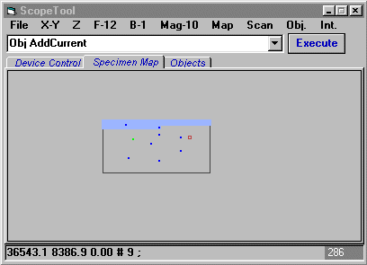
2. Specimen map. Specimen map represents a portion of the specimen at a given zoom level. The map contains scan area, objects, and scan fields. Double clicking on the map moves stage to the point of click.
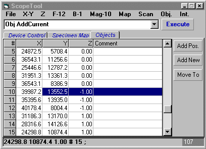
3. Objects list. Current stage and focus position together with comment can be added to the object list and displayed in the specimen map. Coordinates and comment can be edited. Each object can be selected and relocated to. Object list can be written to a file and read from a file.
4. Parameter files are accessible from the corresponding menus. Typically, there is no need to change the supplied parameters. Some parameters may need to be adapted to the user installation, e.g. communication port, or field size.
User interface commands
|
Show |
Load and display the user interface
form. |
|
Hide |
Unload the user interface form. |
Symbolic
constants
The
parameter file ST_SYMCONST.TXT contains name-value pairs that define numerical
values for symbolic constants. These constants can be used in commands instead
of numbers to make them more readable. For example, if this file contains pairs: "DAPI",1 / "FITC",2 /
"CY3",3, then command "F
2" could be written as "F
FITC".
Parameters
describing hardware, specimen, and scanning
Built-in interpreter
Controlling
ScopeTool from different software environments
Integration of components from different vendors in automated microscopy
Low level
controller commands for IM483I
Home > ScopeTool software


